DIGITAL
CAMERA
TABLE OF CONTENTS :
INTRODUCTION
|
There are several different
techniques used to make digital cameras. These techniques result in creating
cameras with differing quality and applicability to a variety of uses.
Understanding the methods used in the camera's design will lead to an
understanding of how successful the camera will be for a particular use.
Historically, this is consistent with the evolution of the camera as a tool.
Over the last 140 years of photography, cameras have evolved into hundreds of
species, ranging from single use pocket cameras to 4x5 studio cameras.
Each camera has unique features that make it especially well suited to a
particular need. When bridging the gap to digital imaging, one must again
consider the need for unique variations that better fit particular requirements.
The quality of an image
produced by a digital camera can be measured in several ways. These include:
resolution, dynamic range and color fidelity. As well, the camera system can
also have several attributes which are important. These include: aperture range,
available focal lengths, illumination alternatives, shutter speeds, ISO
equivalency, portability and battery life. All of these qualities must be
considered when choosing a digital camera.
|
THE BASIC information about
how digital camera works
|
A digital camera is similar
to a film camera except that the film is replaced with an electronic sensor.
The
sensor is made of a grid of photo diodes which change the photons that strike them
into electrons. The electrons are stored in small buckets (capacitors) which are
read out as a series of varying voltages which are proportional to the image brightness.
In the most devices sensor
is CCD (Charge Coupled Device )
The voltage is converted to a number by an Analog to Digital Converter and the
series numbers are stored and processed by a micro processor within the camera, as
you can see on Figure 1.
|
|

Figure
1. |
| In many designs, a mechanical
shutter is used in the same way that it is used in a film camera - to gate the light that
is allowed to reach the sensor or film. Other cameras use what is called an
electronic shutter which allows the control of when the sensor gathers light through
electronic control signals to the sensor. |
A CCD (Charge Coupled
Device) is made up of a large number (several thousand) photoelectric
cells that generate voltage in proportion to the amount of light
striking them. The ability to measure the amount of reflected light is a
very useful property because white and other light colors reflect most
light and black and darker colors absorb most light. In a flatbed or
hand-held scanner, the photoelectric cells are arranged in a line that
is passed over the image to be copied. A light source in the scanner is
directed at the image to be copied and the CCD measures the amount of
light that is reflected. In a camcorder or still videocamera, the
sensors are arranged in a grid rather than along a line and the image is
focused on this grid. The more sensors that are packed into the grid or
along the line, the better the quality of the image that is captured.
Working with color requires an additional enhancement to this system.
Color is captured by passing the light reflected from the image through
colored filters (red, green, blue) before it strikes the CCD and
independently capturing these three sources of information. These three
data sources will later be recombined to reproduce the original image.
If the output from the CCD is to be digitized, a special hardware
converter then takes the voltages generated by the individual elements
of the CCD and rounds them off into the number of alternative values
that will be used to represent the image digitally. If the image is to
be represented as line art, the continuous signal generated by the CCD
elements is rounded off to a value of 1 or 0. If 256 shades of gray or
color are to be represented, the signal from each CCD element is
converted to the appropriate value within this range.
|
Here are different techniques of
performing sensors. According to that fact we have:
The
scanning camera (or camera back)
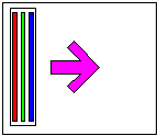 |
This technique involves a
linear array of photodiodes. Typical arrays are either a single row of photodiodes or a
triplet of 3 rows that are covered with red, green and blue dyes, respectively. For color
imaging, if a single column is used, then a color filter set of red, green and blue
filters are moved sequentially into position. The array is positioned in the film plain of
the camera and moved with a motor through thousands of positions. |
Advantages
| This type of camera offers
two principal advantages: First, since linear arrays can be easily obtained with very high
pixel counts (up to 10,000 per color), it is possible to get a very high resolution image.
A second advantage is that these "sticks" can be large enough to
be placed in the film plane of existing 4x5 cameras thereby providing perfect
compatibility with the lenses and camera body already owned by the photographer.
|
Disadvantages
| However, the principal
disadvantage of this type of camera is that it requires a long time to perform a single
image. Therefore, the photographer must use a constant lighting source . It also limits the size of the
object being photographed to one that can be adequately lit. Of course, the second
limitation of this design is that the object being photographed cannot be moving. And,
finally, one can not preview the image in a "video" mode for composition, focus
or lighting since the scanning process is relatively slow. |
Applications
| This camera design is well
suited to graphic arts photography of stationary small objects where the target usage for
the image is either graveur printing or display advertising at large sizes. |
The
one chip moving camera
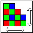 |
The Moving One Chip Camera is
a variant of the scanning camera. It uses an inexpensive "1 Shot" type color
sensor. However, it micro steps it in sub-pixel amounts in both the X and Y
direction. As a result, with some computation, one is able to build a high quality
color image with minimal aliasing. |
Advantages
| This technique offers
moderate cost and very high resolution. |
Disadvantages
| The scanning speed and
re-ordering of data makes it quite slow. As such it requires HMI (Continuous)
lighting and is therefore not acceptable for many types of product shots. |
Applications
| This camera design is well
suited to graphic arts photography of stationary small objects where the target usage for
the image is either graveur printing or display advertising at large sizes. |
The
one chip camera - the "color 1 shot"
 |
The "One Chip" color
camera uses a single 2 dimensional Photodiode array. The array is covered with a set of
miniature color filters, red, green and blue, which cover individual pixels in a
predefined pattern. Various patterns have been used. A popular pattern, called the Bayer
pattern, uses a square for 4 cells that include 2 green on one diagonal, 1 red and one
blue on the opposite diagonal. |
Advantages
| This type of camera is the
least expensive to build. It can also be used for live action photography. |
Disadvantages
 |
The principal disadvantage is
an image artifact called color aliasing. This occurs when an object that is being
photographed has a feature which is so small that it only covers less than 3 color pixels.
The result is that the real color of the object is impossible to ascertain since one has
only partial color information. This causes a miss coloration in the image that may appear
as a colored dot in the hair or a colored fringe on a sharp edge. |
Applications
| This camera design is well
suited to web design, identification and badging, low resolution printing and consumer
usage. |
The
three chip color camera
 |
This type of camera uses a
beam splitter to separate the incoming image into three component images which are sent to
three independent sensors simultaneously. A beam splitter is a set of semi-transparent
mirrors that reflect part of the image and transmit part. Some beam splitters can
separate the colors of an image in this way as well. |
Advantages
| This camera can shoot moving
objects in color. It offers excellent resolution with no color aliasing.
It is
compatible with all types of lighting. (except for low frequency fluorescent which may
beat with the electronic shutter) |
Disadvantages
| The cost of building this
type of camera is high due to the triplication of the sensor and the strict tolerance for
alignment of the three sensors. As well, the method used for splitting the image can
result in the addition of various artifacts like secondary images or non-ideal spectral
response. |
Applications
| This camera design is well
suited to graphic arts applications where moderate resolution is required. |
The
one chip / Three shot camera
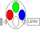 |
This type of camera uses a
monochrome sensor and a rotating color filter wheel with 4 positions. The neutral
position is used for focusing and composition and then three successive pictures are taken
through each of the three filters: red, green and blue. |
Advantages
| The Three Shot Camera has the
advantage of allowing the use of either strobe or ambient illumination.
Thus, the
photographer has the convenience of staging shots with equipment that they are accustomed
to. The availability of strobe allows greater flexibility of the use of the aperture
for depth of field. This design provides excellent resolution with no color
aliasing. Additionally, this design can be accomplished at relatively low
cost. |
Disadvantages
| This type of camera can only
shoot stationary objects in color but it can shoot moving objects in
monochrome. |
Applications
| This camera design is well
suited to graphic arts photography of stationary objects where the target usage for the
image is either web or offset press at moderate to large sizes. |
Importaint
features
- RESOLUTION
- PRINT SIZE
- ALIASING
- DYNAMIC RANGE
- BLOOMING
RESOLUTION
| In
the most basic sense, the resolution of a digital camera can be stated to be the total
number of pixels used. For example, a camera with a sensor that has
800 by
1000 pixels can be said to have 800,000 pixels of total resolution. |
 |
A good way of visualizing
this is to think of mosaic tile art where each mosaic tile can be only a single color and
brightness. A single tile can be considered to be equivalent to a single
pixel. For digital images, the tiles are arranged in neat rows and columns.
When the art (or image) is perceived from a distance, the nature of the individual tiles
(or pixels) are lost and the image as a whole is appreciated. |
BACK
PRINT SIZE
| Once you determine the true
resolution of the camera, this still leaves open the issue of "how large can I print
the image?" This requires an understanding of the limitation of the print media
that is used. For example, if your target is an offset press at a 133 line screen,
then 800,000 pixels of image data should be adequate for approximately 8 by 10 inches.
More image data won't show a discernable difference in the print.
Alternatively, if your target output is a newspaper with a 100 line screen, then the
target image size for the same 800,000 pixel image can be as large as 11 by 14 inches.
The best way to determine the maximum printable size is to test the process with
your printer. However, as a rule of thumb, we have found that roughly .8 pixel per
line rule is required to hold resolution.
Continuous tone printers must be considered differently. Each dot of a
continuous tone printer is in fact, one full color pixel. Therefore, maximum
resolution requires a one to one ratio between input and output pixels. In these cases,
the limitation often winds up being the resolving ability of the viewer.
As a
point of interest, a 20 year old can see approximately 2000 pixels across 8 inches viewed
at reading distance of approximately 1 foot. The size of an "8x10"
print and a magazine page are probably what they are because they fill the viewers field
of view when viewed at a comfortable reading distance of about 1 foot.
Likewise,
when you look at a 4x5 print, you typically hold it closer so as to fill your field of
view as well.
For Web output, image requirements are
quite low. Images are typically considered to be 72 dpi continuous tone.
Thus,
an 800 x 1000 image would occupy a screen area of approximately 11 by 14 inches, far too
large for most applications. |
BACK
ALIASING
Single chip color cameras have a problem known as color aliasing. This occurs when a region of sharp contrast is imaged with a color mosaic CCD array. Figure
2. shows a white block on a black background for our original image. The black/white transition lies directly between pixels as shown in the center image. On the right you can see the resulting image from a single CCD camera. The turquois region results from the fact that some color pixels are generated by quadrants of RGB pixels where the white exposes only blue and green pixels. The yellow color pixels are produced by exposing only the red and green pixels. Regions where the RGB pixels are equally exposed are white and regions where no pixels are exposed are black.
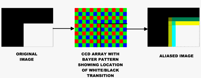
Figure 2. The Black and White Image (left) Has Color Aliasing in at Edges When Imaged with a Color CCD.
Color aliasing is demonstrated in Figure 3. A small region of the image on the left side is magnified to the point where individual pixels can be seen (right image). The rainbow effect at the edges is color aliasing. The color abnormalities in color aliasing confuses machine vision systems
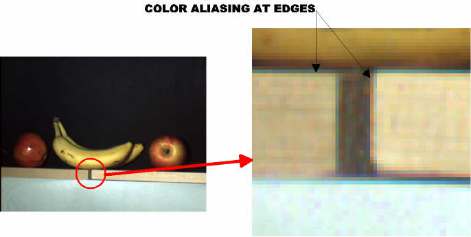
Figure 3. A Magnified Region of the Image on the Left Shows Color Aliasing at the Edges of Objects.
BACK
DYNAMIC RANGE
 |
A more difficult aspect of
imaging to understand is the measurement of dynamic range. Using the mosaic tile
analogy again, this can be considered to be the number of different colors (or shades of
gray for a monochrome case) that can be selected from, when choosing individual tiles.
For example, for 24 bit color, each tile could have one of 256 x 256 x 256 colors
or 16,777,216 different colors.
When designing a digital
camera, the dynamic range relates to both the accuracy of the A/D converter that changes
the analog voltage representing a pixel brightness to a digital number, and the noise
present in the system. Typical cameras have A/D converters of 8 bits or 256 different
discernable levels. Better cameras have 10, 12 or even 14 bit A/Ds.
The dynamic range
will interpret into your ability to observe fine gradations in the darkest shadow areas of
an image or equivalently in the brightest highlights. Better cameras will preserve the
color and texture even into the shadow areas. How much you need again relates to
your output media and what details of the image you are interested in preserving.
|
BACK
BLOOMING
| There are some special
artifacts that are present in digital cameras that are not found (or are differently
manifested) in conventional film photography. The most noticeable is Blooming.
Blooming occurs when a pixel receives too much light
What happens to the
extra electrons is what is important, in well designed cameras, the overflow is
properly siphoned off without affecting neighboring pixels. In less well designed
systems, the extra charge is allowed to spill into neighboring pixels thereby spreading
the size of the highlight. If the spread is non uniform, as is typically found in a
scanning camera, then the artifact can be quite disturbing since it appears as an
unnatural stripe in the image.
|
BACK
EXAMPLE
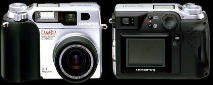
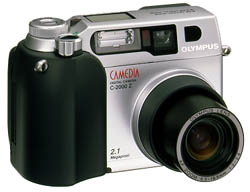
OLYMPUS CAMEDIA C-2000 ZOOM
If you want to find out about other Olympus products click on the left
side of the picture, if you woud like more inormation about C-2000 click on the
right side of the picture.
| Product type |
Digital camera (for shooting and displaying) |
| Recording System |
Digital recording (JPEG/TIFF) |
| Memory |
3.3V SmartMedia 2MB, 4MB, 8MB, 16MB, 32MB |
| No. of storable pictures |
1 shot (TIFF, 8MB)
7 shots (SHQ, 8MB)
15 shots or more (HQ, 8MB)
38 shots or more (SQ/XGA, 8MB)
122 shots or more (SQ/VGA, 8MB) |
| Erase |
One-frame erase / All-frames erase |
| Image pick up element |
1/2 inch CCD solid state image pickup
2 110 000 pixels (gross) |
| Recording image |
1600 x 1200 pixels (HQ/SHQ/TIFF)
640 x 480 pixels (SQ mode/VGA)
1024 x 768 pixels (SQ mode/XGA) |
| White balance |
Full auto TTL, Manual (daylight, overcast,
tungsten light, flourescent) |
| LCD monitor |
1.8" (4.5 cm) TFT color LCD display |
| No. of pixels |
Approx. 114 000 pixels |
| On-screen display |
Date/Time, Frame number, Protect, Recording
mode, One/All erase, Battery check, Information display, Menu, Random
print. |
| Battery charging time for flash |
Approx. 6 sec. (at normal temperature with new
batteries) |
| Flash working range |
Wide: Approx. 0.8 to 5.6 m
Tele: Approx 0.2 to 3.8 m |
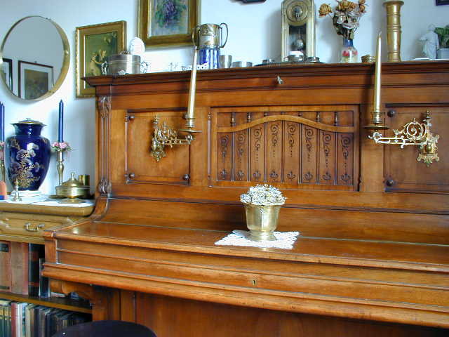
PICTURE TAKEN WITH C-2000 : HQ FORMAT (1600 X 1200 PIX.)

PICTURE TAKEN WITH C-2000 SQ FORMAT (640 X 480 PIX.)
REFERENCES
Richard A. Perez : ELECTRONIC DISPLAY DEVICES
A.Šantić : BIOMEDICINSKA ELEKTRONIKA
Olympus Camedia C-2000 : OWNER'S MANUAL
Niedermeyer Winter katalog 1999
www.olympus-europa.com
www.olympus.com


